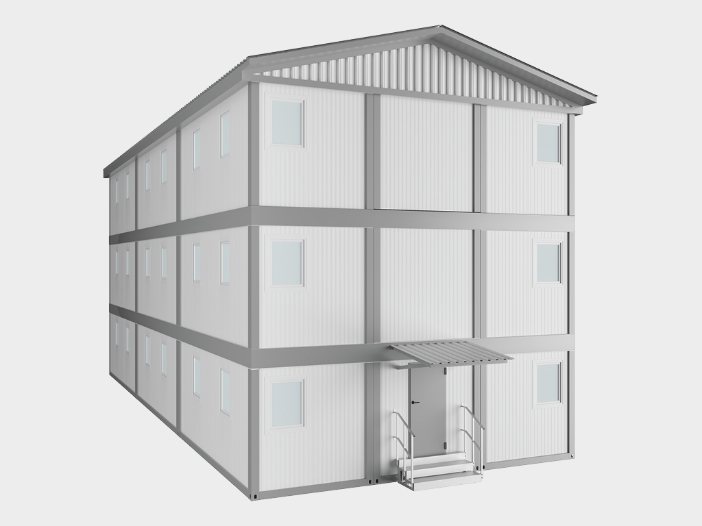
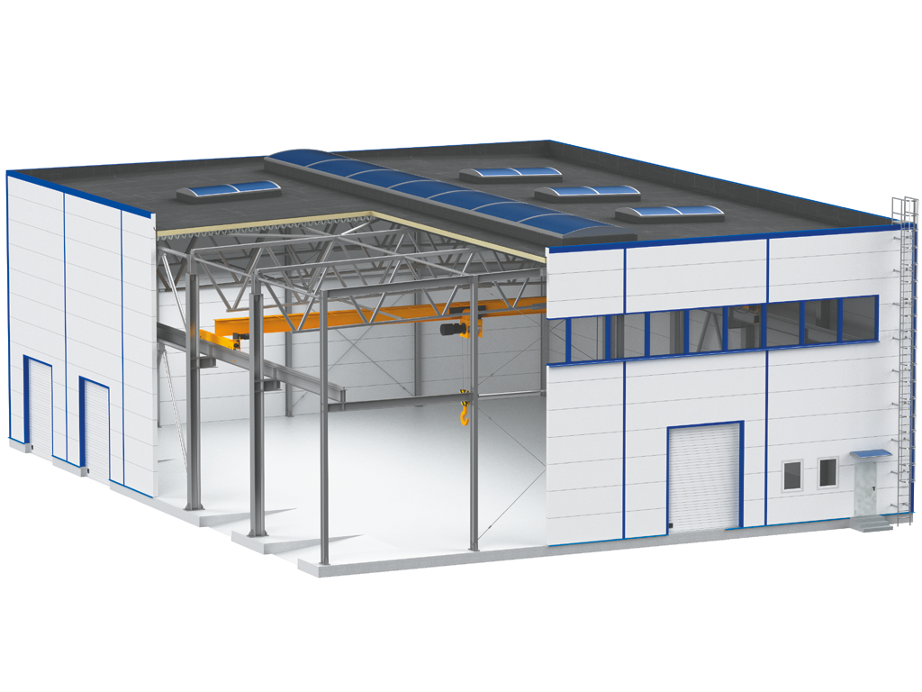
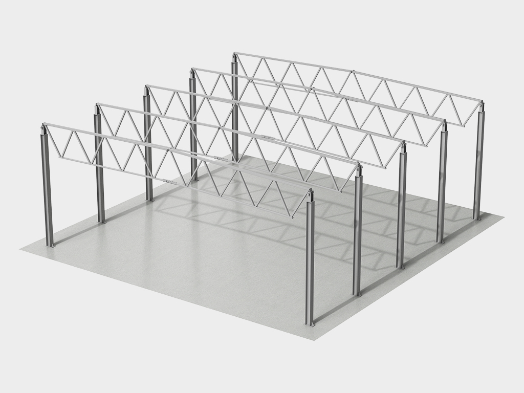
Yirik sanoat, omborxona yoki qishloq xo'jaligi ob'ektlarini qurish haqida gap ketganda, qurilish tezligi, konstruksiya ishonchliligi va iqtisodiy samaradorlik asosiy omillarga aylanadi. DoorHan konserni ushbu barcha talablarga ideal javob beradigan zamonaviy va texnologik yechim — yassi tomli ferma tipidagi karkasli binolarni taqdim etadi. Biz shunchaki metall konstruksiyalar to'plamini emas, balki oraliqlari 24 metrgacha bo'lgan binolarni eng qisqa muddatlarda qurish imkonini beruvchi, yig'ishga to'liq tayyor bo'lgan "konstruktor"ni taklif etamiz.
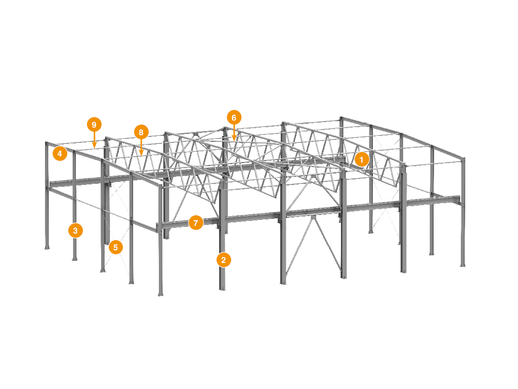
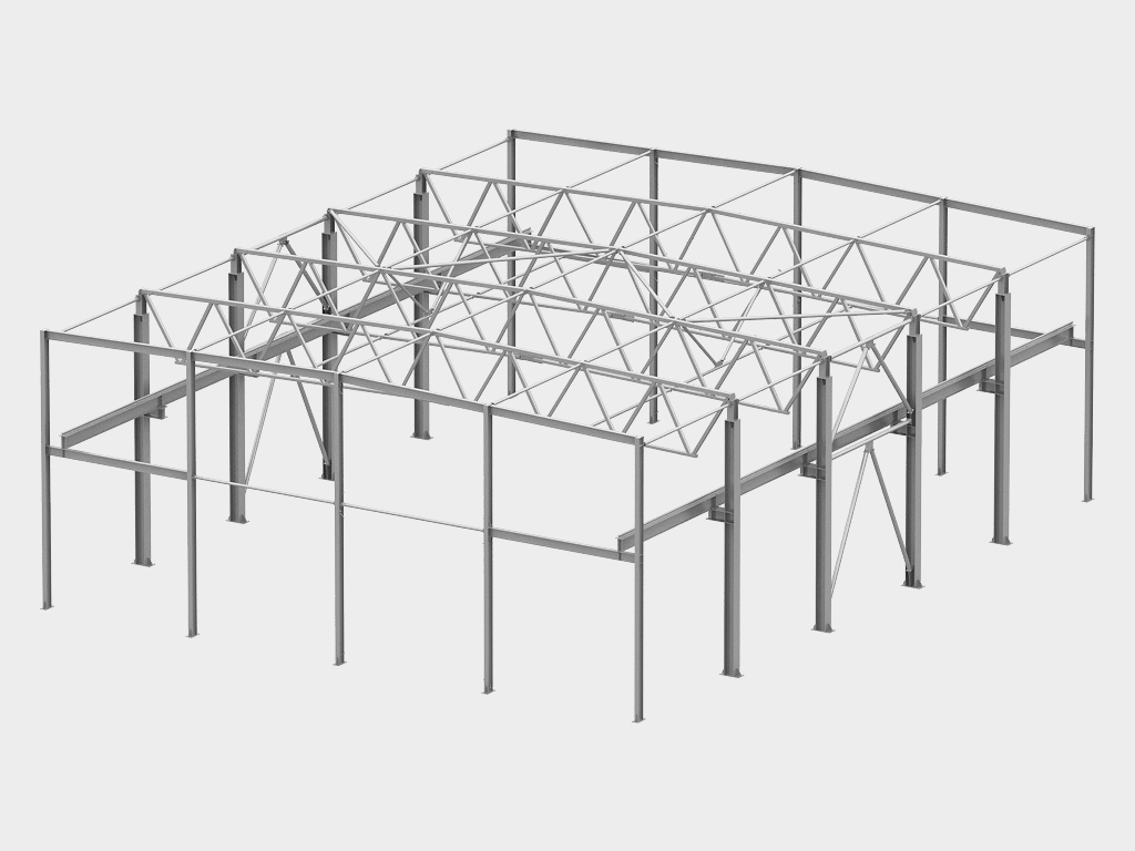
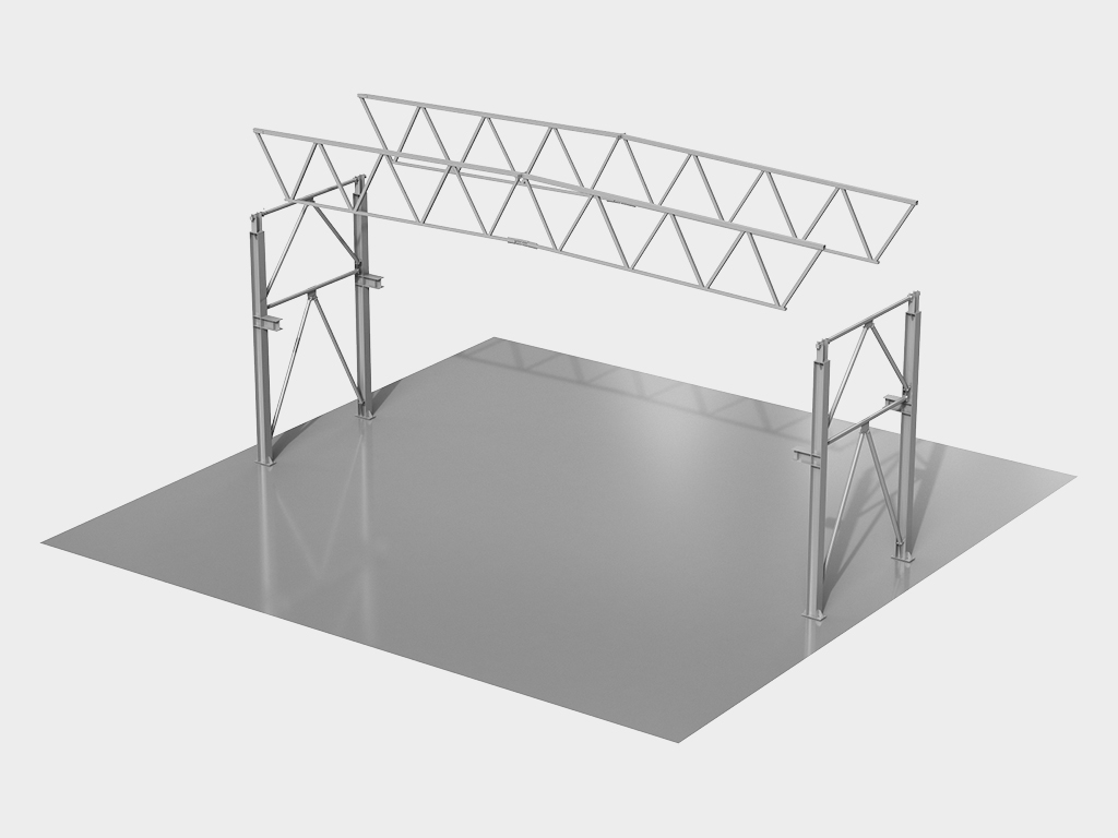
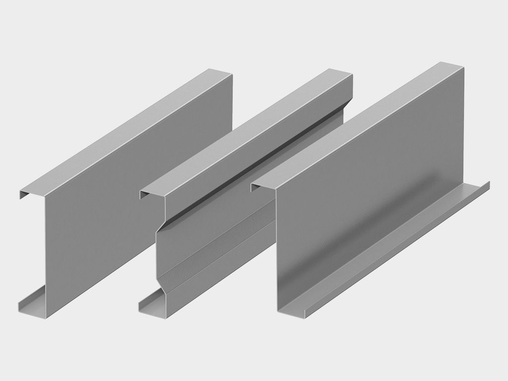
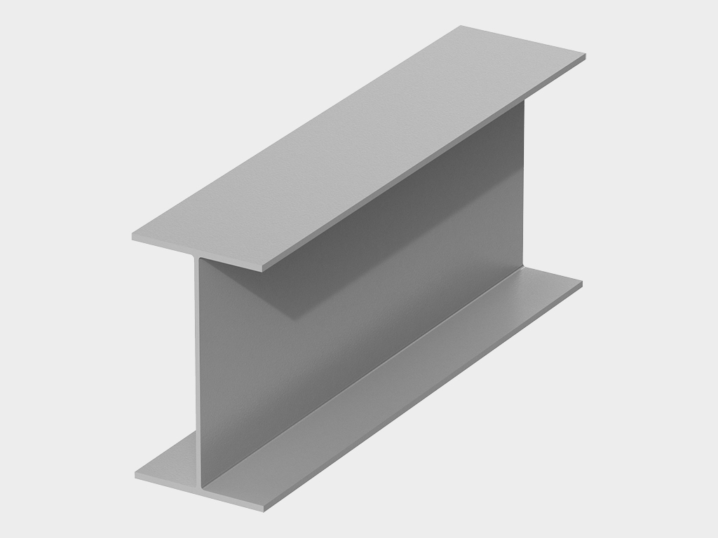
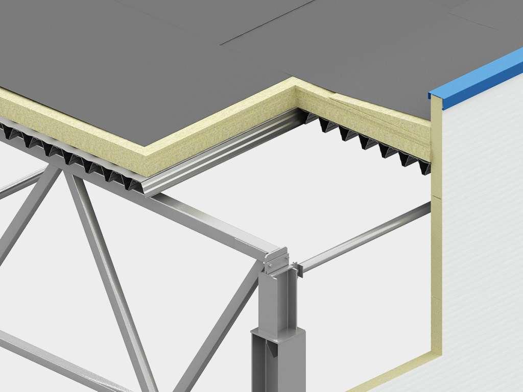
Mustahkamlik asosi — ferma konstruksiyasi. Ikki tavrli balkalar asosidagi binolardan farqli o'laroq, tomning yuk ko'taruvchi elementlari sifatida po'lat fermalardan foydalanish bir qator shubhasiz afzalliklarni beradi:
- Yengillik va tejash: Ferma — bu minimal og'irlikda maksimal mustahkamlikni ta'minlaydigan muhandislik konstruksiyasidir. Bu karkasning umumiy metall sig'imini sezilarli darajada kamaytiradi, bu esa butun binoning narxini pasayishiga olib keladi. Bundan tashqari, kamroq og'irlik poydevorga tushadigan yukni kamaytiradi, bu uni yengilroq va tejamkorroq qilish imkonini beradi.
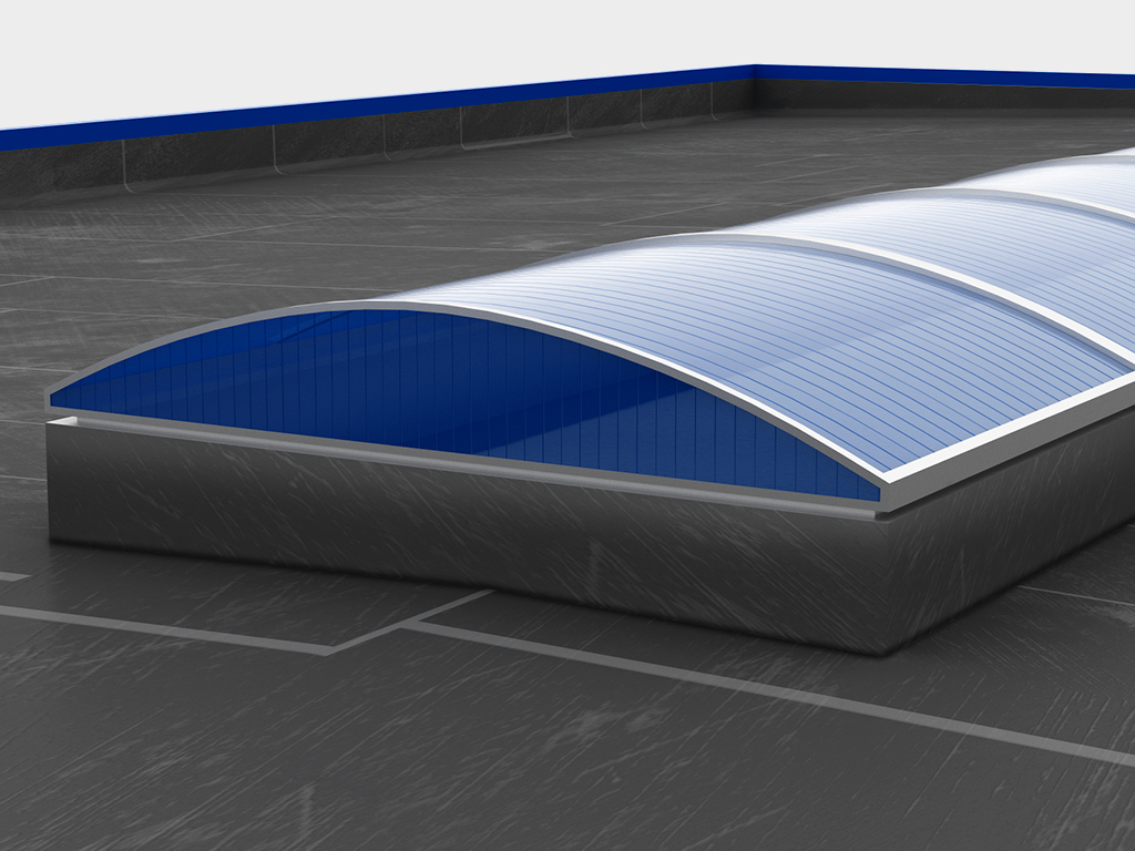
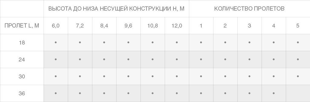
- Katta tayanchsiz oraliqlar: Ferma texnologiyasi oraliq ustunlarni o'rnatmasdan katta oraliqlarni (24 metrgacha) osongina yopish imkonini beradi. Bu sizga maksimal samaradorlik bilan foydalanish mumkin bo'lgan mutlaqo erkin ichki makonni beradi.
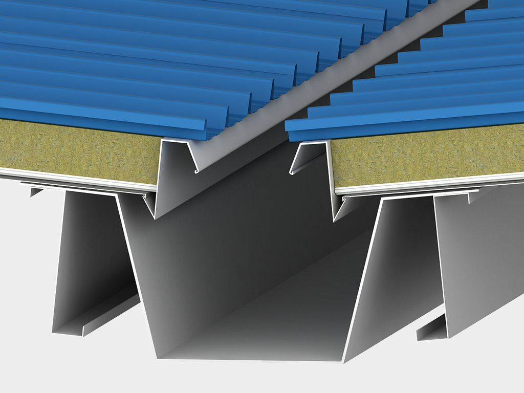
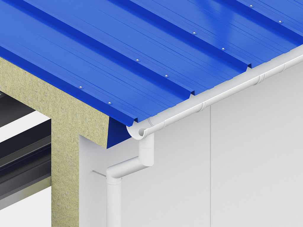
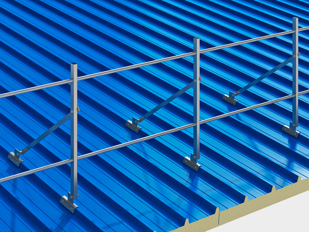
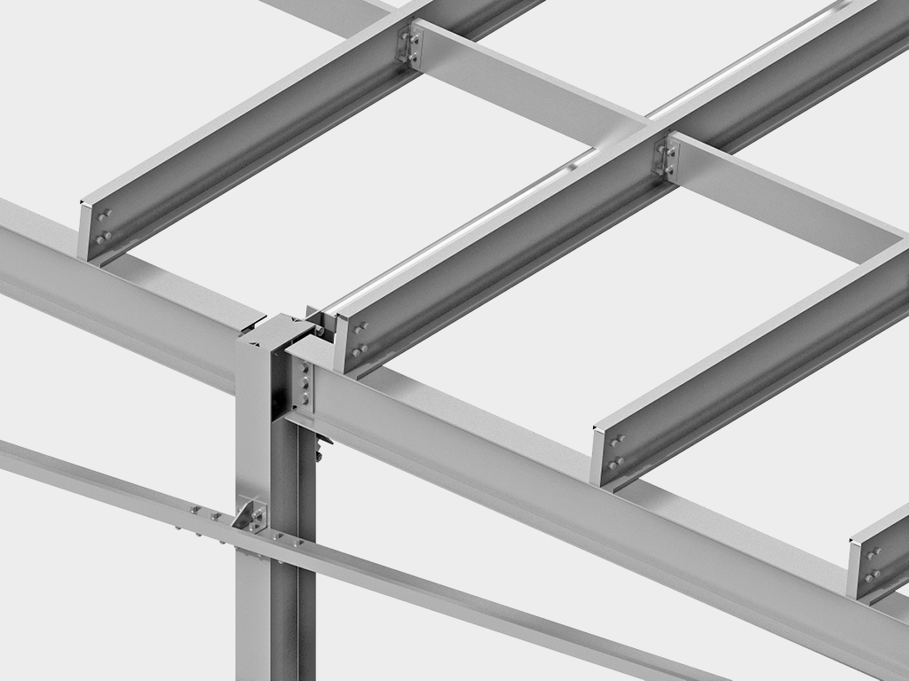
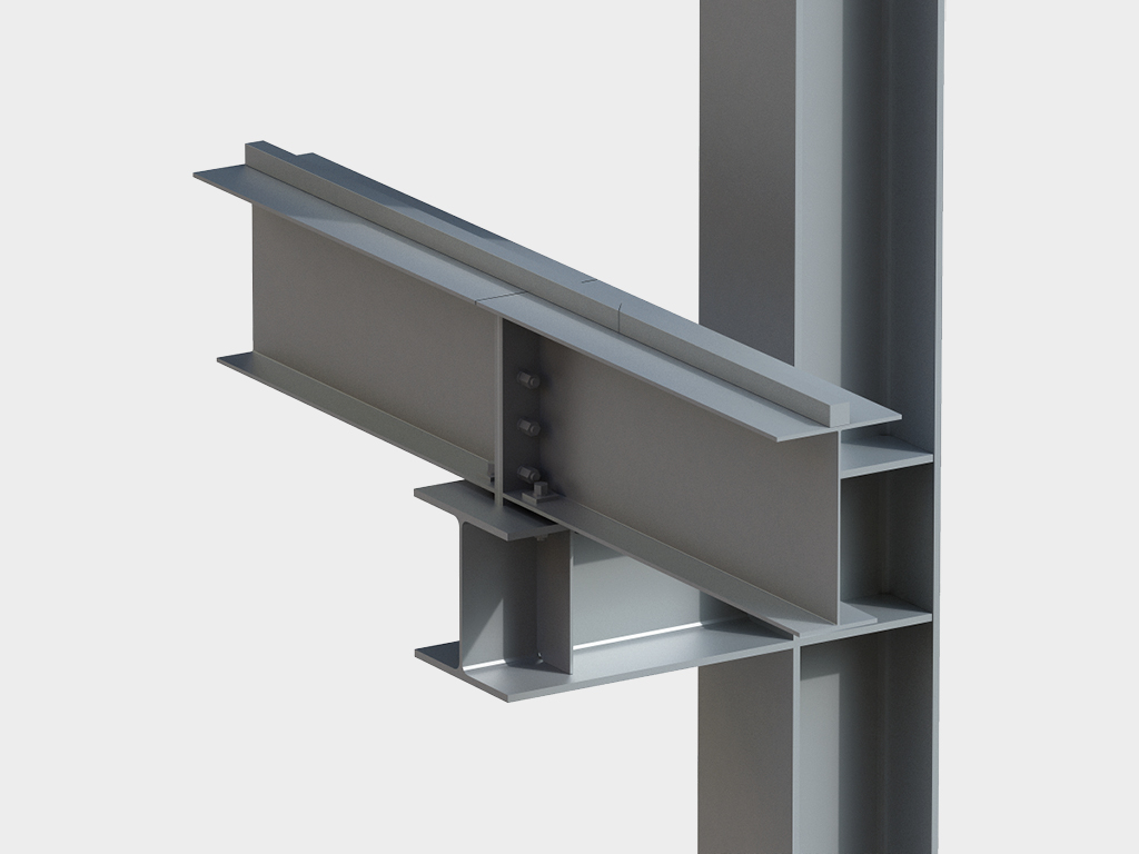
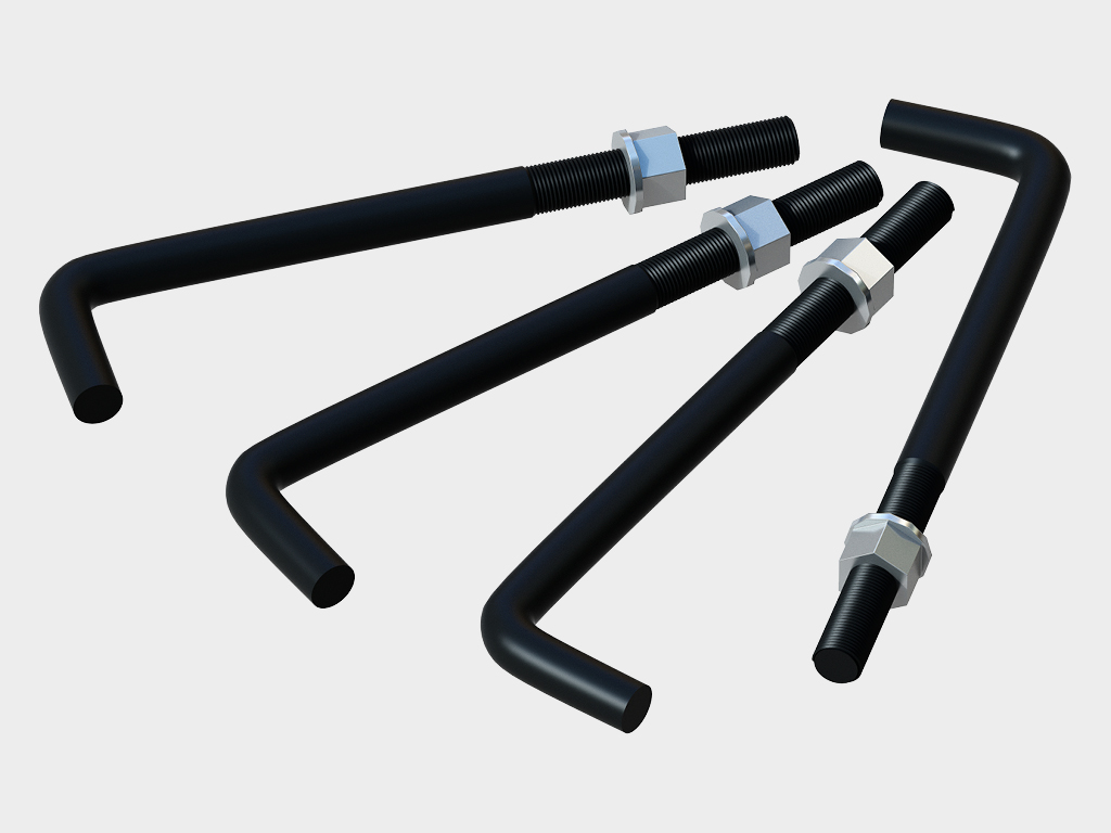
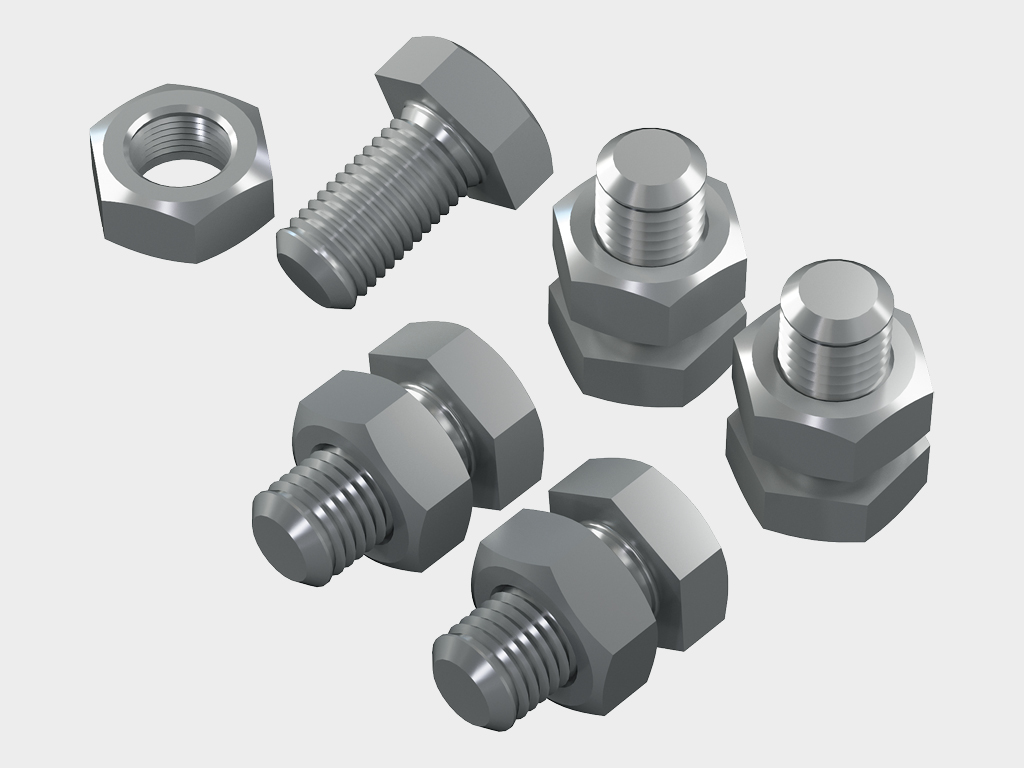
Hisob-kitoblar bilan tasdiqlangan ishonchlilik. Har bir binomiz — bu aniq muhandislik hisob-kitoblari natijasidir. Karkasning barcha elementlari — ustunlar, fermalar, progonlar va bog'lamlar — ikki bosqichli korroziyaga qarshi ishlovdan o'tgan (drobemyot tozalash + kukunli bo'yash) yuqori sifatli po'latdan yasalgan. Bu konstruksiyaning chidamliligini va har qanday atmosfera ta'sirlariga chidamliligini kafolatlaydi. Barcha birikmalar yuqori mustahkamlikdagi boltlar bilan amalga oshiriladi, bu "ho'l" jarayonlarni istisno qiladi va montajni har qanday ob-havoda olib borish imkonini beradi.
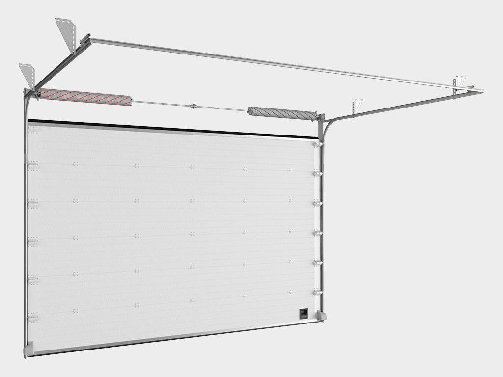
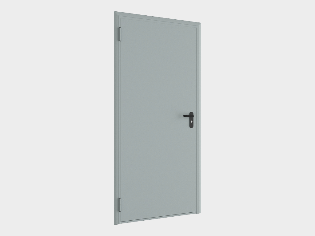
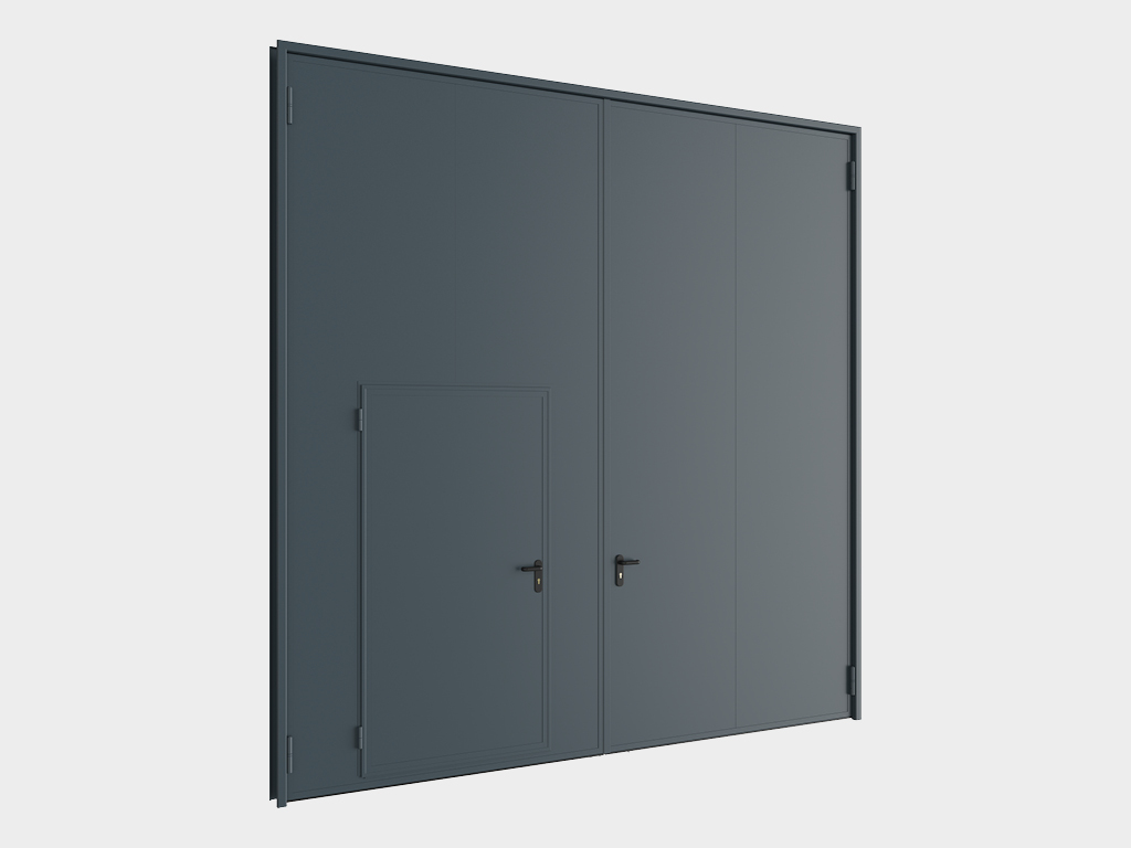
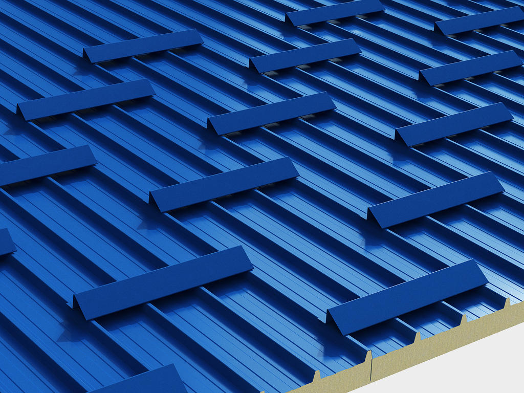
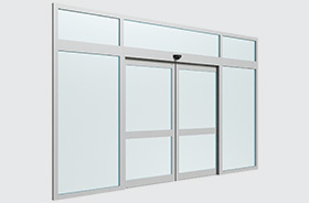
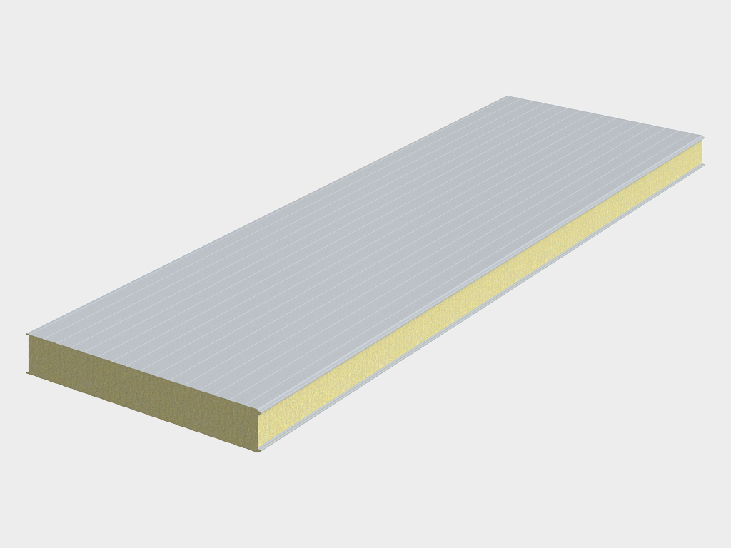
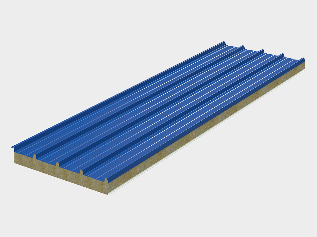
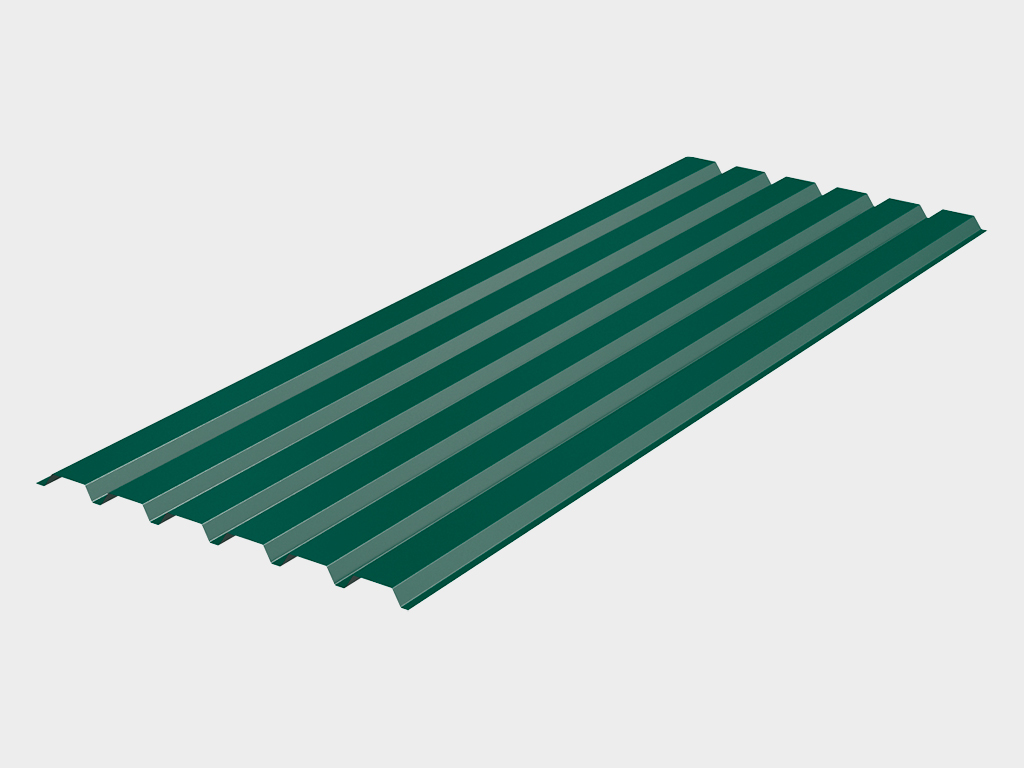
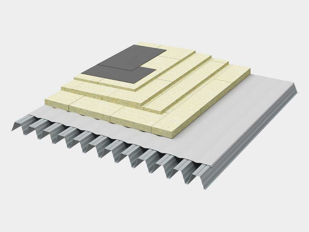
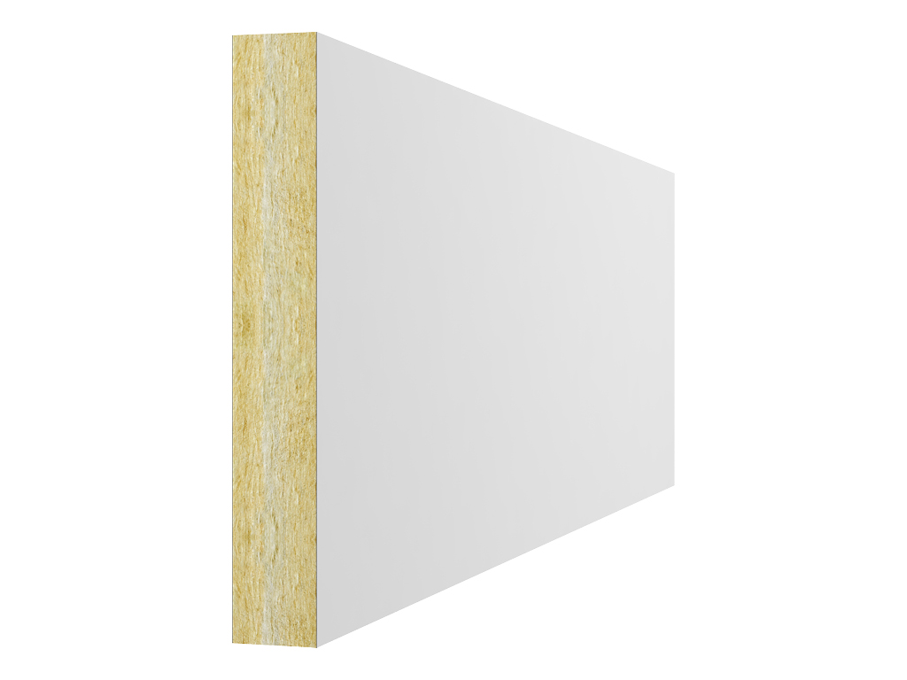
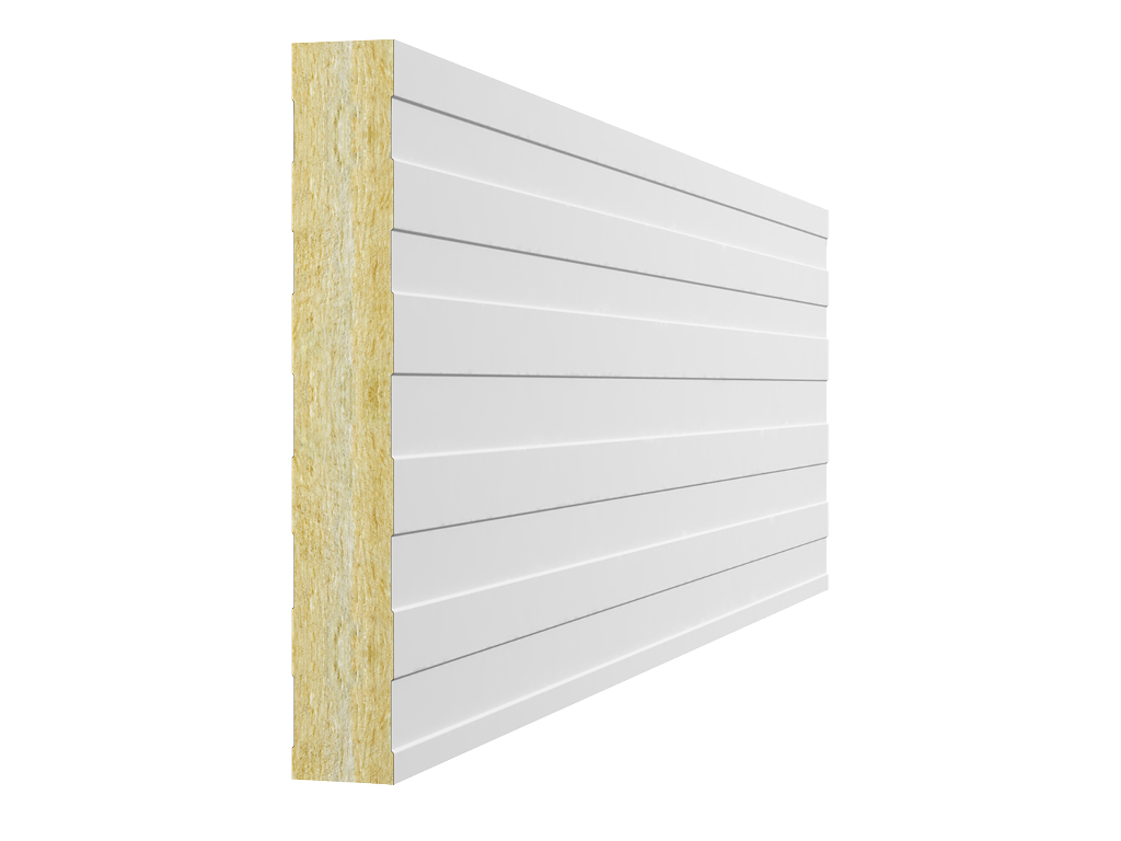
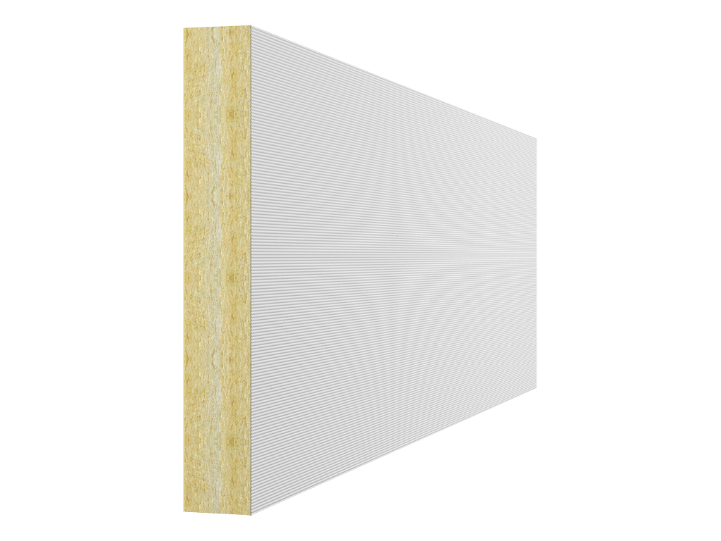
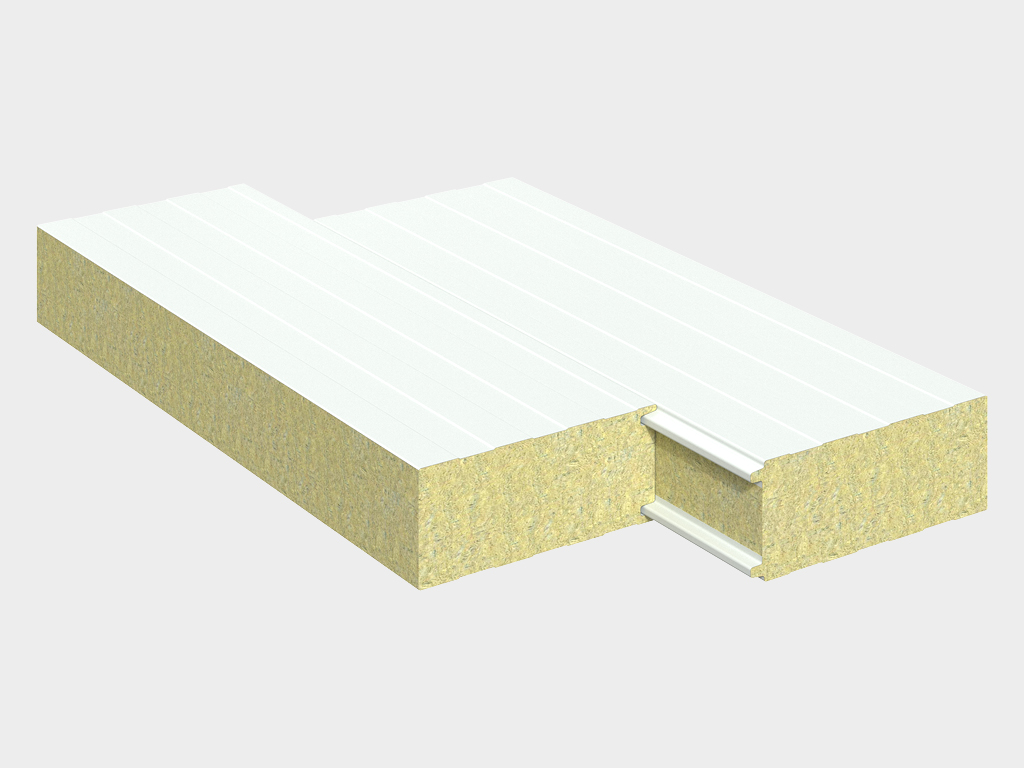
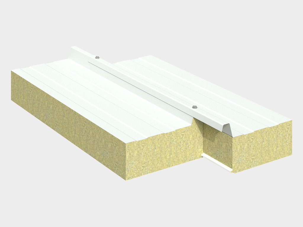
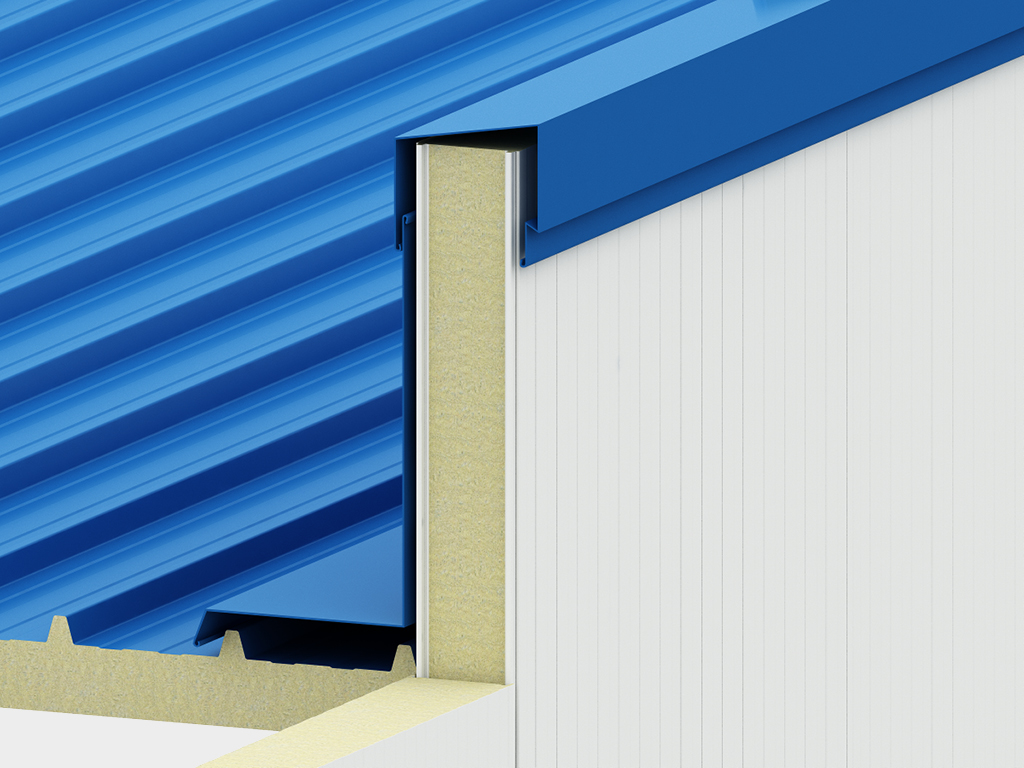
Bitta ishlab chiqaruvchidan kompleks yondashuv. Biz nafaqat karkasni yetkazib beramiz. Bizdan bino buyurtma qilib, siz foydalanishga tayyor bo'lgan to'liq jihozlangan ob'ektga ega bo'lasiz. To'plamga bizning o'zimizning ishlab chiqarishimiz bo'lgan devor va tom sendvich-panellari, shuningdek, barcha zarur qo'shimcha va mahkamlash elementlari kiradi. Ammo eng muhimi — biz sizning binoingizni barcha kerakli DoorHan uskunalari bilan darhol jihozlay olamiz: sanoat darvozalari, eshiklar, yuk ortish tizimlari va hokazo. Bu barcha elementlarning 100% mosligini kafolatlaydi va sizni o'nlab turli yetkazib beruvchilar bilan ishlash zaruratidan xalos qiladi. DoorHan karkasli binolarini tanlab, siz soha yetakchisidan tezlik, tejash va kompleks ishonchlilikni tanlaysiz.
.jpg)