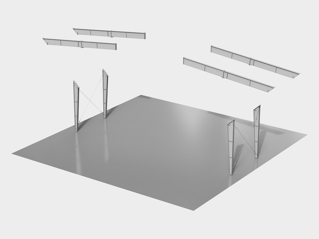
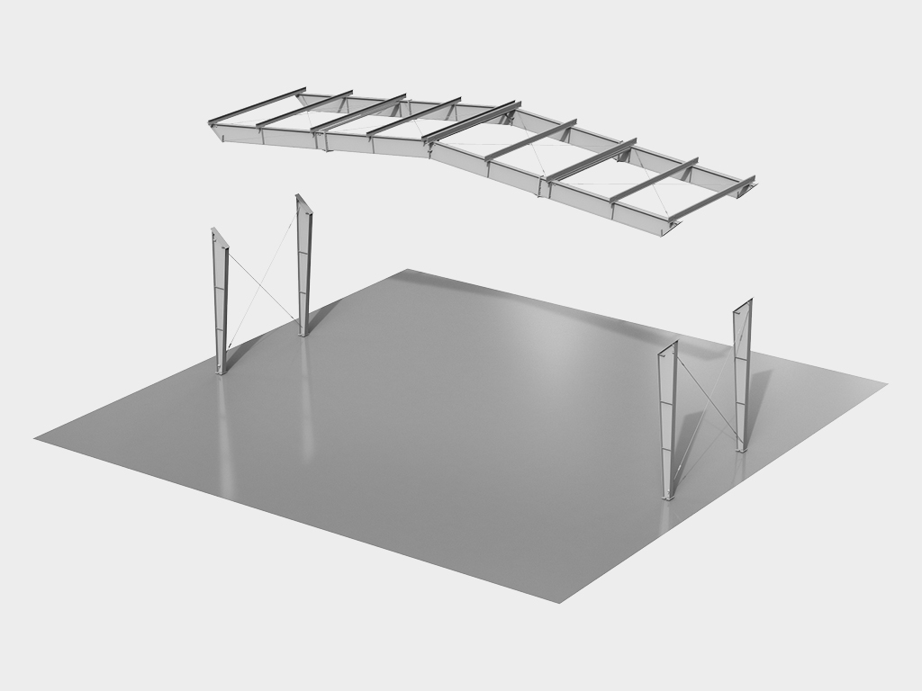
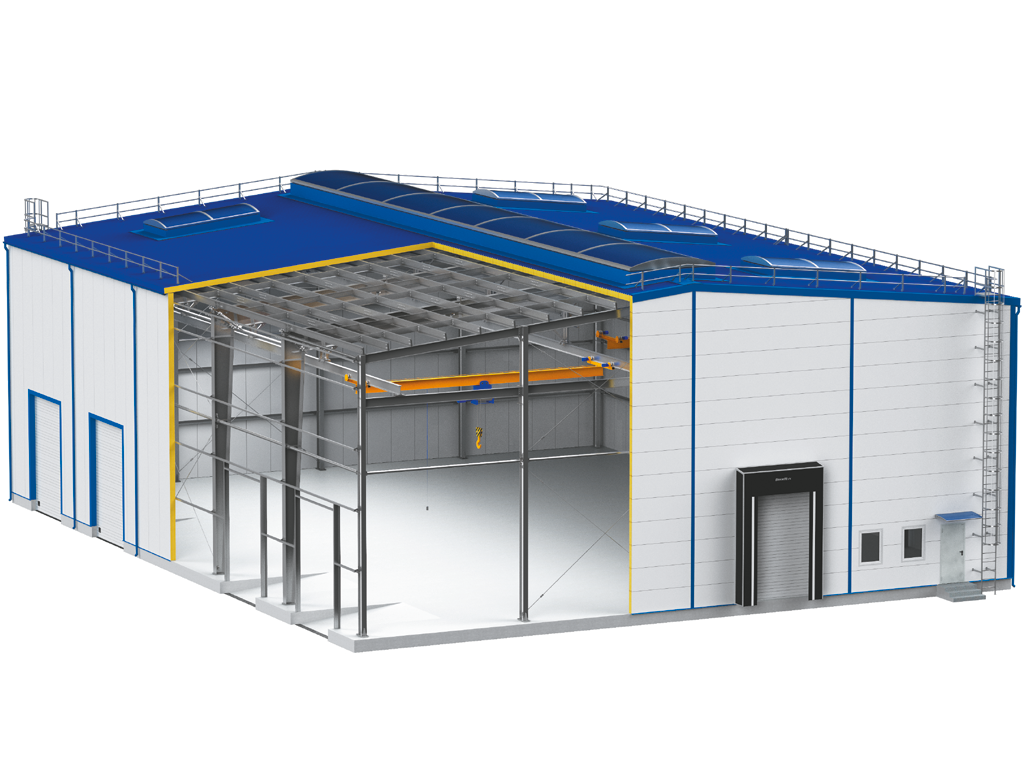
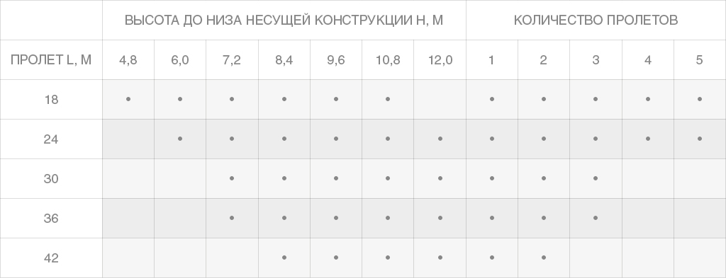
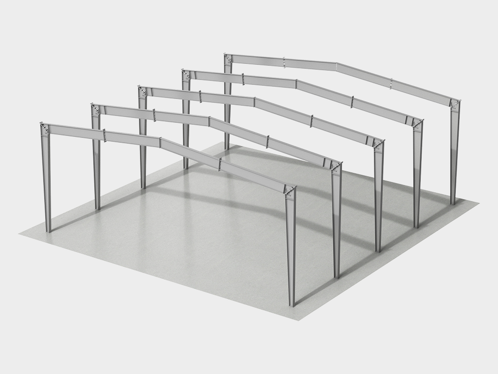
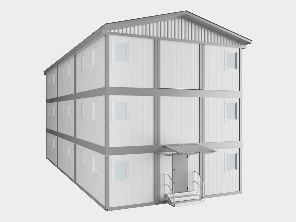
Klassik arxitekturadagi binolarni qurish haqida gap ketganda — angarlar va omborxonalardan tortib qishloq xo'jaligi majmualari va savdo pavilyonlarigacha — ikki nishabli tom eng amaliy va vaqt sinovidan o'tgan yechim hisoblanadi. DoorHan konserni ikki nishabli tomli rama tipidagi karkasli binolarni taqdim etadi. Bu asosida ikki tavrli balkalardan yasalgan kuchli karkas yotadigan, oraliqlari 24 metrgacha bo'lgan ishonchli va chidamli binolarni tez va samarali qurish imkonini beruvchi kompleks, yig'ishga tayyor yechimdir.
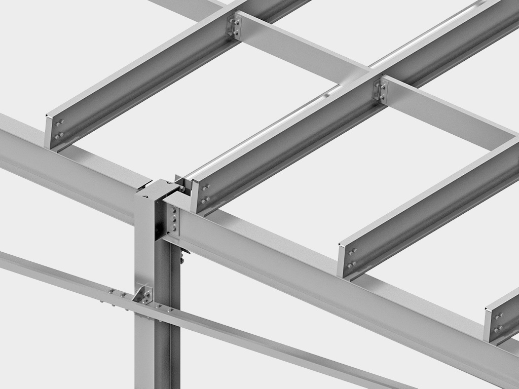
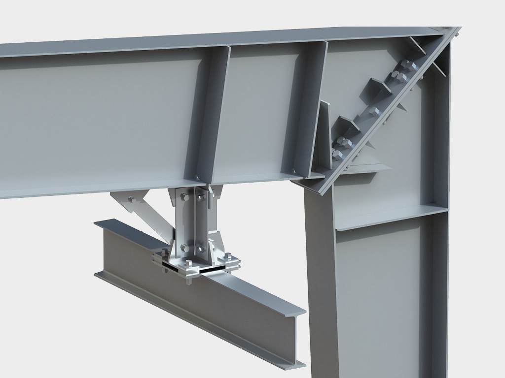
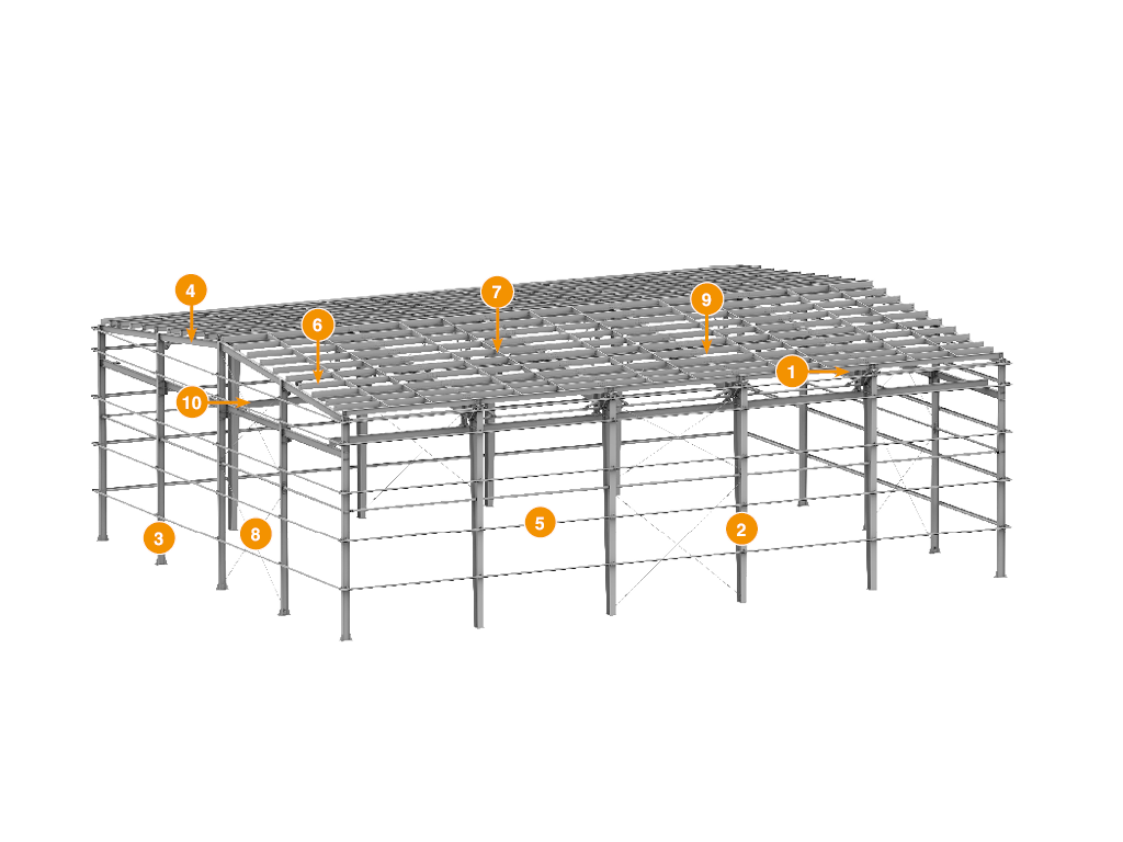
Fundamental mustahkamlik: ikki tavrli karkas. Ferma konstruksiyalaridan farqli o'laroq, yuk ko'taruvchi elementlar (ustunlar va rigellar) sifatida payvandlangan ikki tavrli balkalardan foydalanish o'z afzalliklariga ega:
- Maksimal yuk ko'tarish qobiliyati: Ikki tavrli balka ulkan mustahkamlikka ega va juda yuqori yuklamalarga bardosh bera oladi. Bu bunday karkaslarni, masalan, kran-balkalar kabi og'ir osma uskunalarni o'rnatish rejalashtirilgan binolar uchun ideal yechimga aylantiradi.
- Soddalik va montaj tezligi: Rama konstruksiyasi fermaga nisbatan kamroq yirik elementlardan iborat, bu qurilish maydonchasida yig'ish jarayonini tezlashtirishi mumkin.
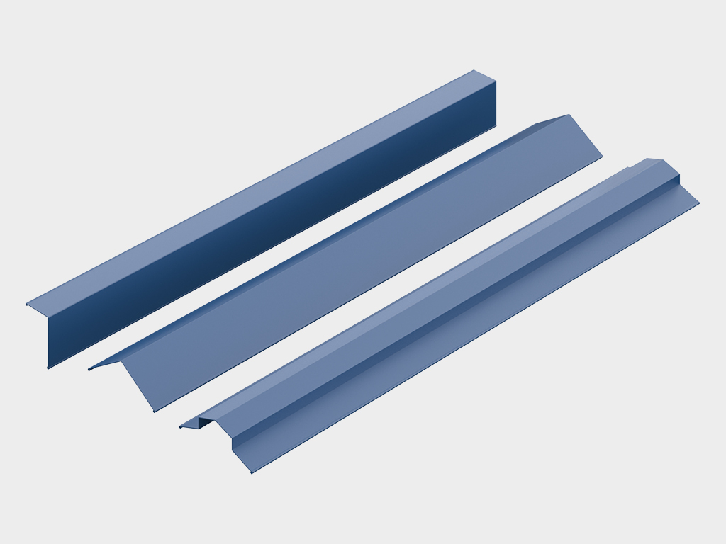
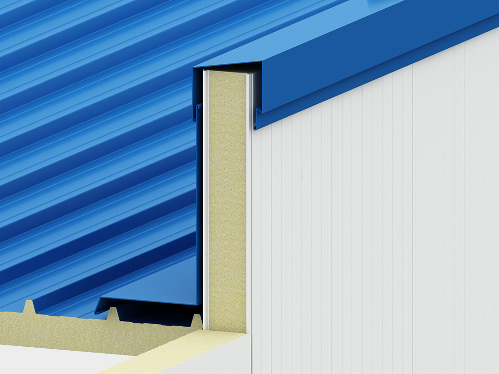
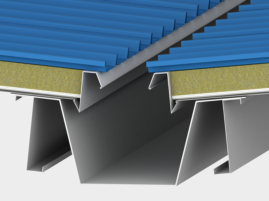
Ishlab chiqarishda poydevor qo'yilgan ishonchlilik. Biz binolarimizning eng yuqori sifati va chidamliligini kafolatlaymiz. Karkasning barcha elementlari yuqori sifatli po'latdan yasaladi va ikki bosqichli korroziyaga qarshi ishlovdan o'tkaziladi: avval ideal yopishish uchun drobostruy tozalash, so'ngra mustahkam kukunli bo'yoq bilan qoplanadi. Barcha birikmalar yuqori mustahkamlikdagi boltlar bilan amalga oshiriladi, bu ob'ektda payvandlashni istisno qiladi va montajni har qanday ob-havoda olib borish imkonini beradi.
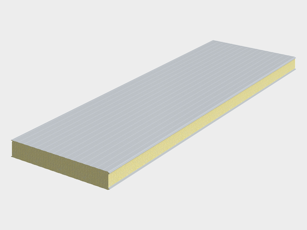
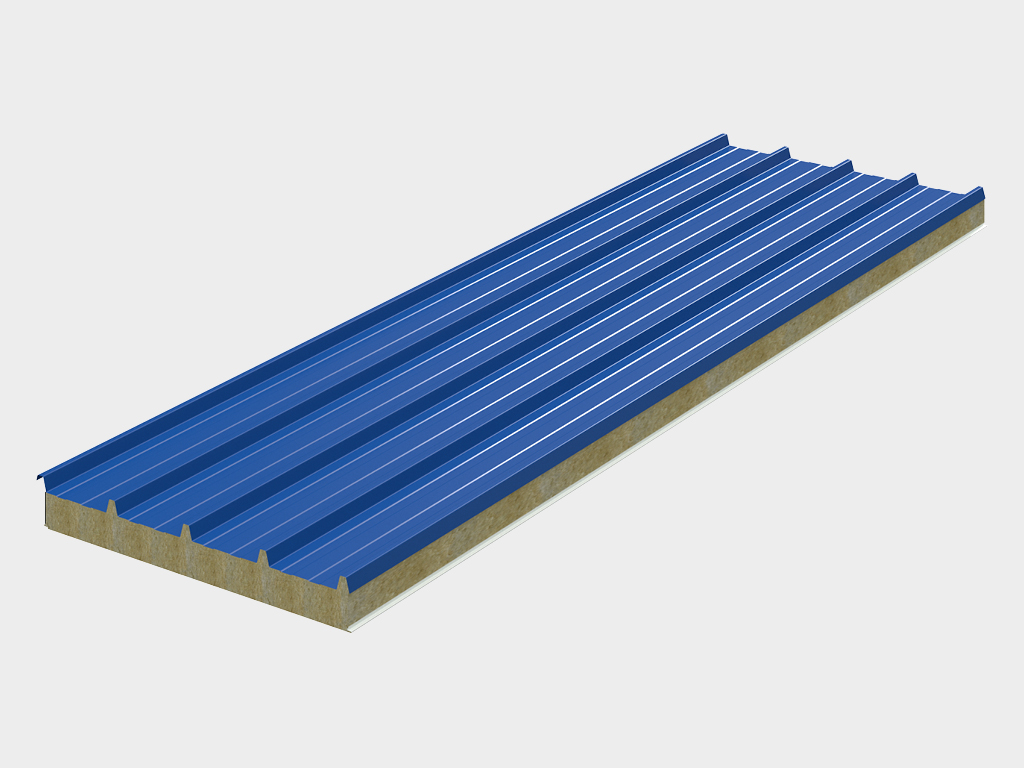
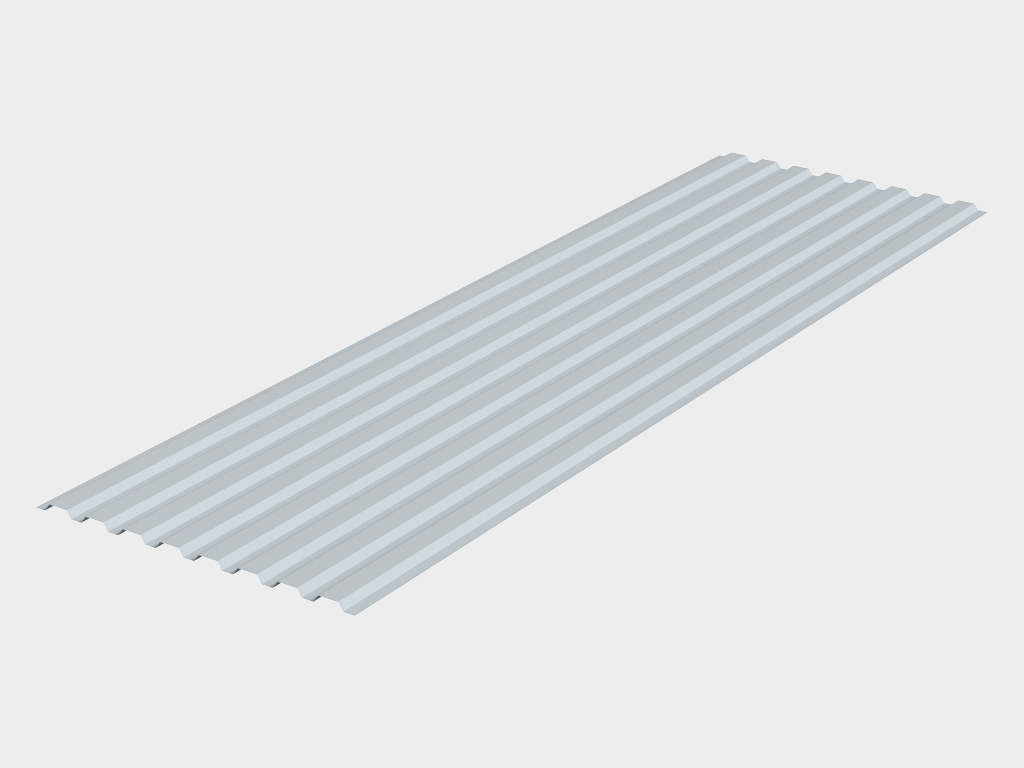
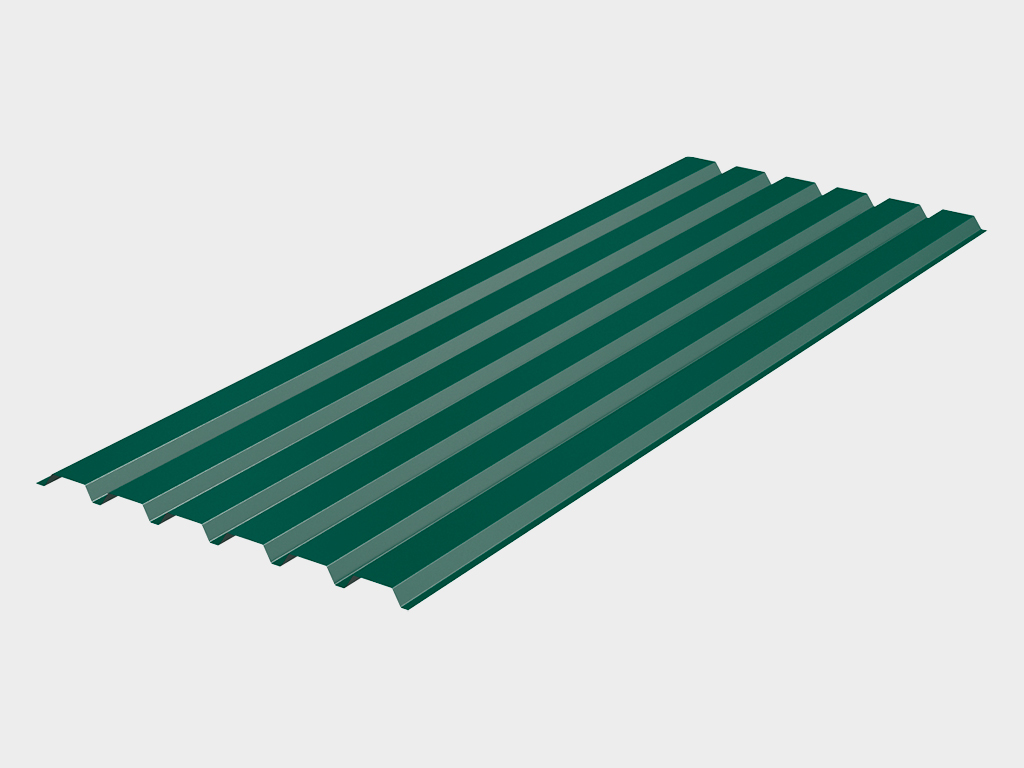
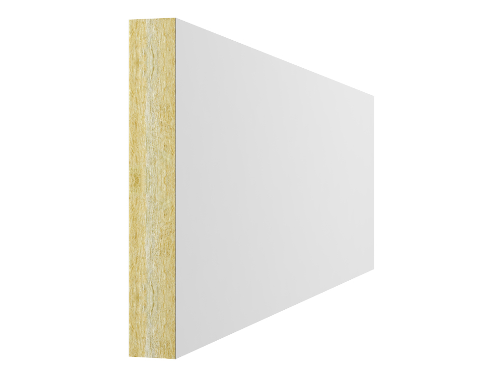
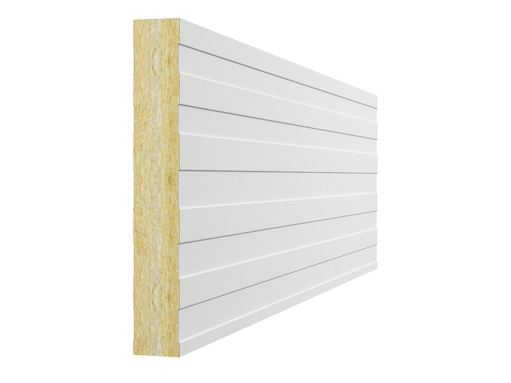
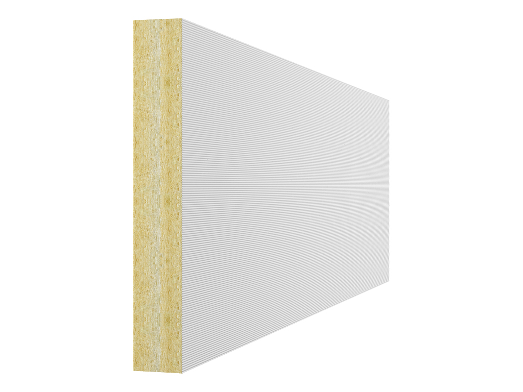
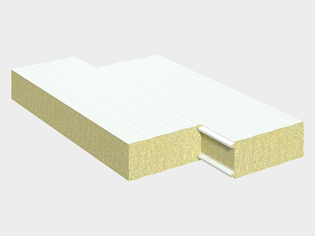
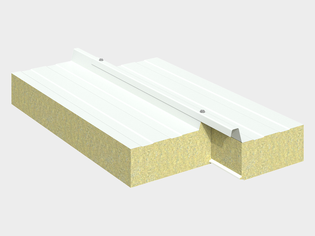
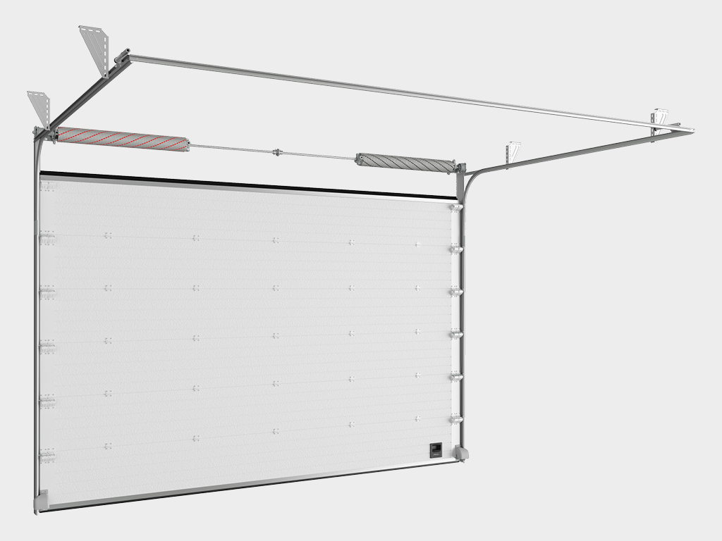
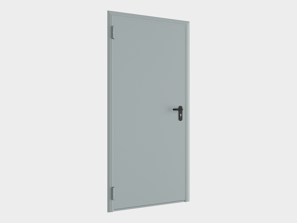
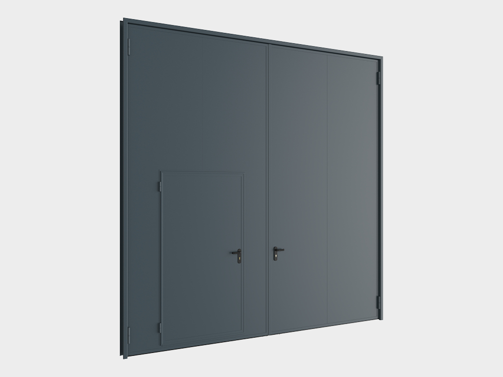
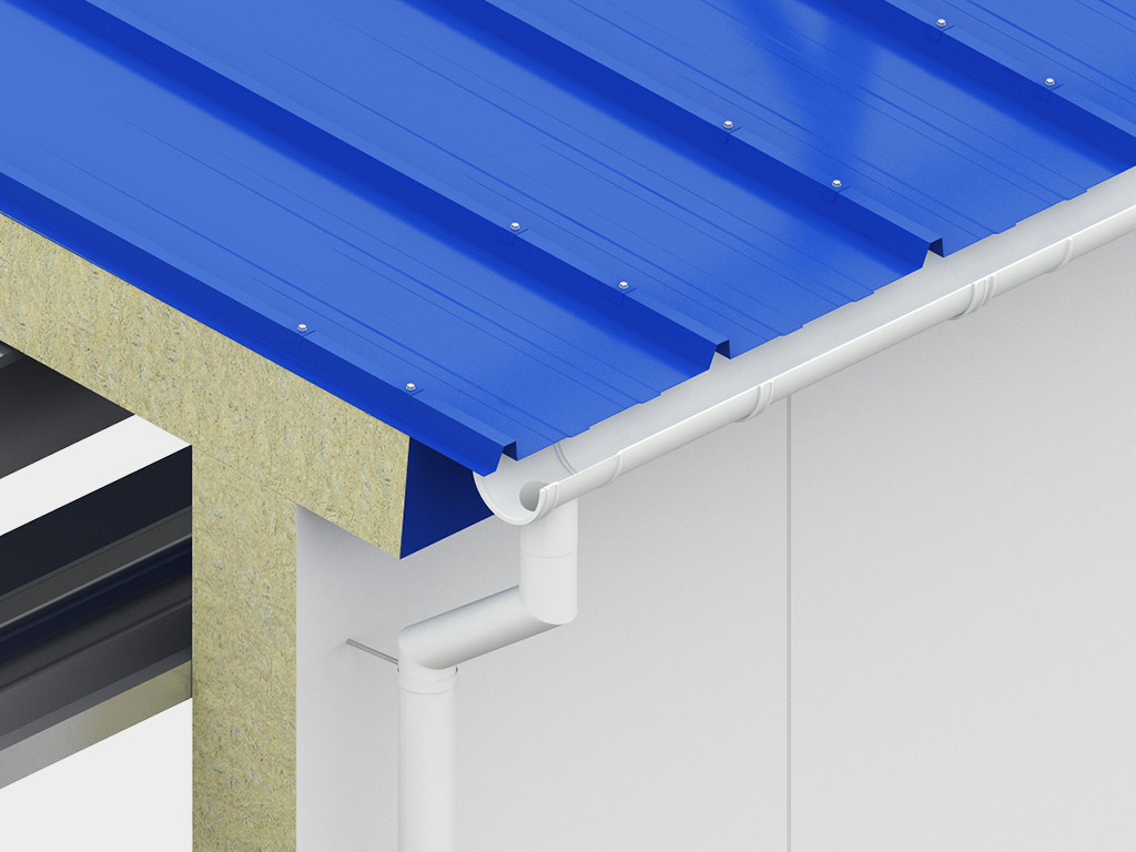
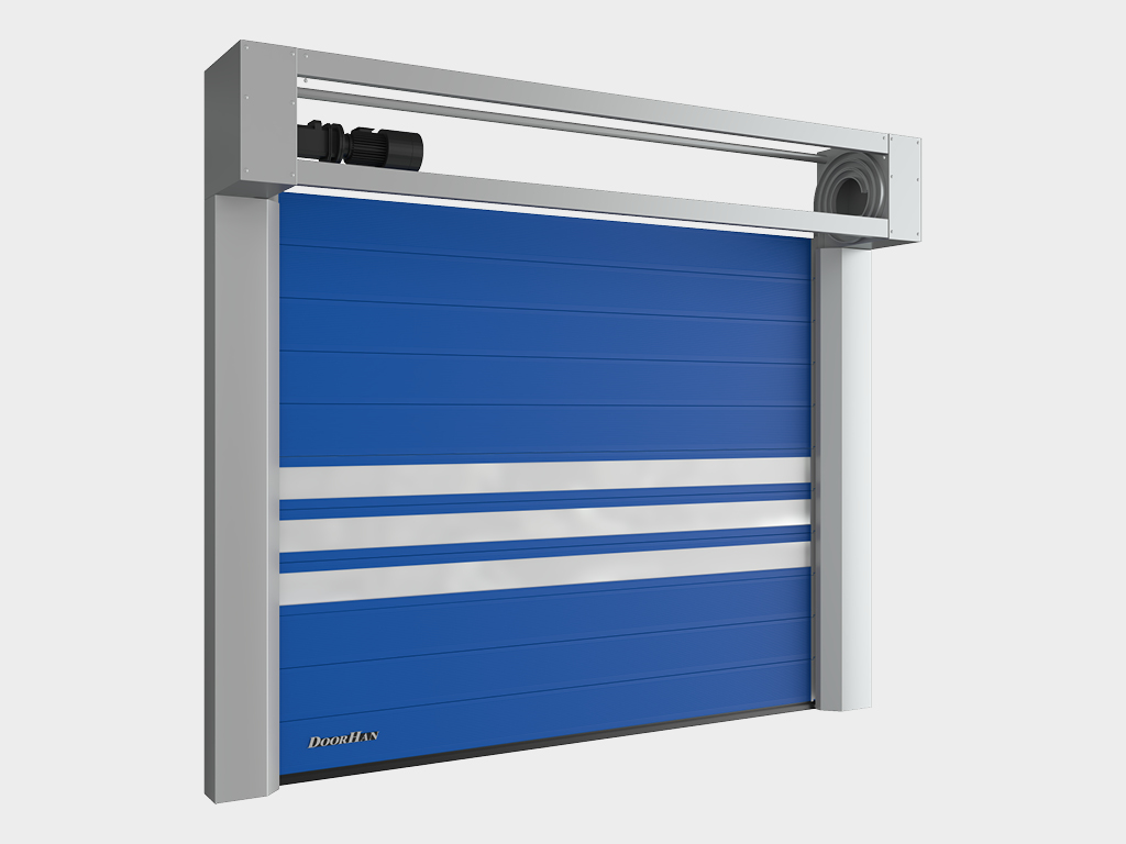
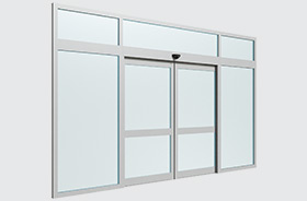
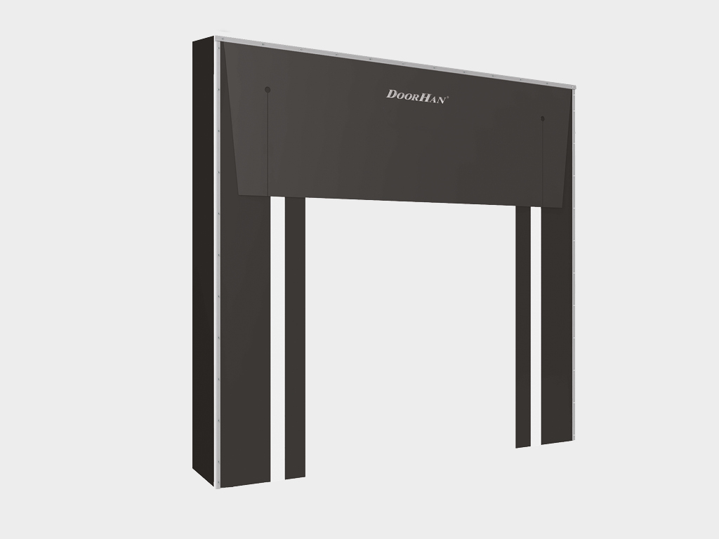
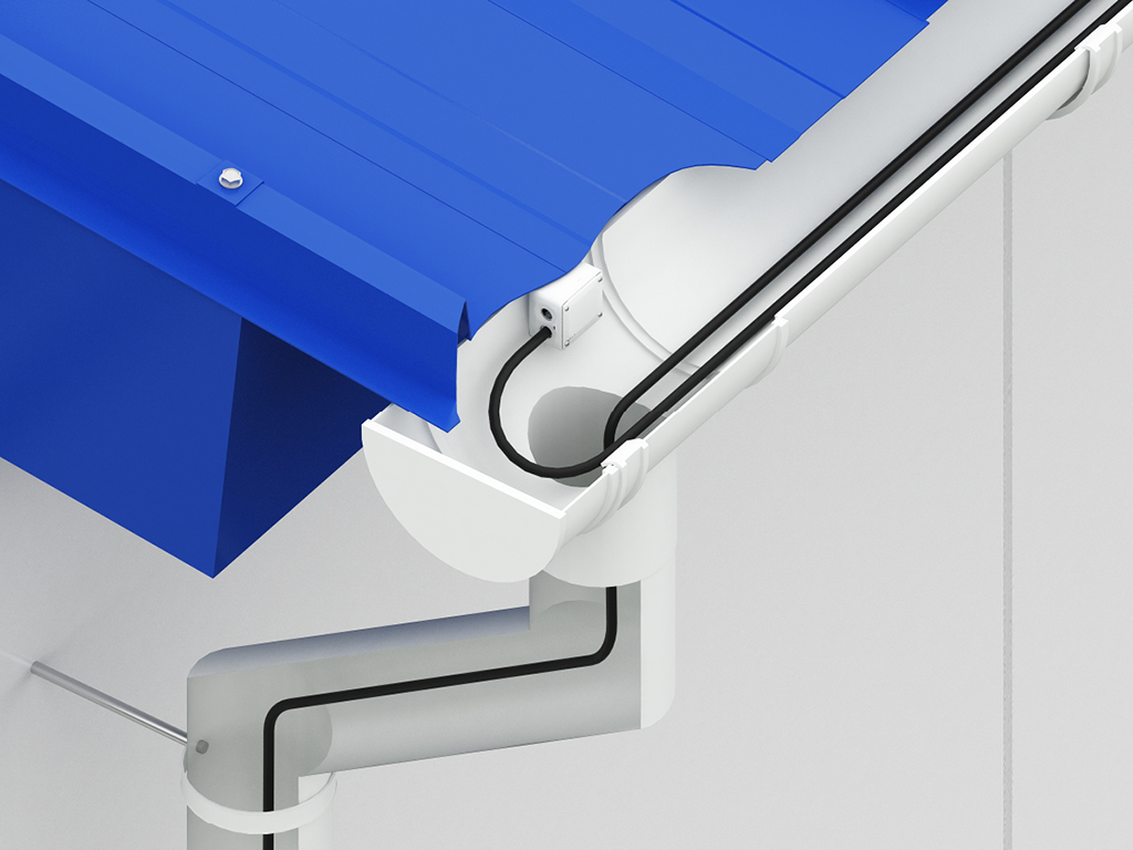
Bitta ishlab chiqaruvchidan kompleks yondashuv. Bizdan bino buyurtma qilib, siz shunchaki metallokarkasga emas, balki to'liq jihozlangan ob'ektga ega bo'lasiz. Yetkazib berish to'plamiga bizning o'zimizning ishlab chiqarishimiz bo'lgan devor va tom sendvich-panellari, shuningdek, barcha zarur qo'shimcha va mahkamlash elementlari kiradi. Ammo eng muhimi — biz sizning kelajakdagi binoingizni barcha kerakli DoorHan uskunalari bilan darhol jihozlay olamiz: sanoat darvozalari, eshiklar, yuk ortish doklari va hokazo. Bu barcha elementlarning 100% mosligini kafolatlaydi va sizni o'nlab turli yetkazib beruvchilar bilan ishlash zaruratidan xalos qiladi. DoorHan'dan rama tipidagi karkasli binolarni tanlab, siz zamonaviy texnologiyalar va kompleks yondashuv bilan kuchaytirilgan klassik ishonchlilikni tanlaysiz.
 — копия.jpg)
.jpg)
.jpg)